In this article, I will explain you all about pattern allowances and how to calculate different pattern allowances for designing the pattern for metal casting.
1. Pattern
A pattern is a replica of the object to be made by the casting process, with some modifications
The main modifications are:
- Addition of pattern allowances,
- Provision of core prints, and
- Eliminating fine details which cannot be obtained by casting.
2. Pattern Allowances - Their Types
The dimensions of the pattern are made greater than the dimensions of the final casting product. This is because of various reasons discussed below:
2.1 Shrinkage Allowance
All metals shrink when they are cooled (except Bismuth). However, there is a distinction between liquid shrinkage and solid shrinkage.
To account for liquid shrinkage, risers are provided in the moulds.
The Shrinkage allowance is provided to take care of the reduction in volume due to Solid Shrinkage.
Solid Shrinkage is the reduction in volume when the metal changes from liquid to solid state at the solidus temperature.
Rate of contraction depends on:
- Material
- The metallurgical transformation taking place during solidification.
The actual value of shrinkage depends on various factors specific to a particular casting:
- The actual composition of alloy cast,
- Mould Materials used,
- Mould Design,
- The complexity of the pattern and the component size.
Important points
- As a rule, all the dimensions are going to be altered uniformly unless they are restrained in some way. For example, a dry sand core at the centre of the casting may restrain the casting from contracting but the edges are not restrained. Thus it may be desirable to provide a higher shrinkage allowance for outer dimensions compared to ones which may be restrained.
- The pattern maker's experience and a little bit of trial are to be used in arriving at the final shrinkages provided on the pattern.
- The shrinkage allowance is always added to the linear dimensions. Even in case of internal dimensions (e.g. internal diameters of cylinders), the material has a tendency to contract towards the centre and thus are to be increased.
- It is also possible to obtain shrink rulers for specific materials such as steels which are nothing but special scales where dimensions are shown are actually longer by a measure equal to the shrinkage allowance. Dimensions provided by such a rule can be used at the time of making the pattern. Different shrink rulers are used for different casting materials.
| # | Material | Pattern Dimensions mm | Shrinkage Allowance mm/m |
|---|
| 1 | Grey Cast Iron | up to 600
600 to 1200
over 1200 | 10.5
8.5
7.0 |
| 2 | Plain Carbon Steel | up to 600
600 to 1800
over 1800 | 21.0
16.0
13.0 |
| 3 | Chromium Steel | - | 20.0 |
| 4 | Manganese Steel | - | 25.0 to 38.0 |
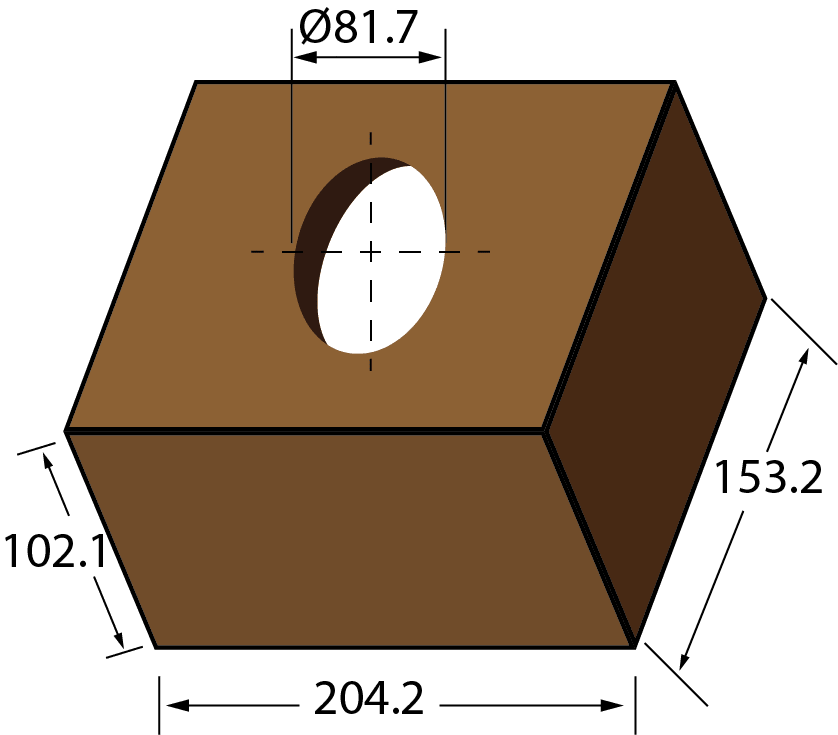
Question 1
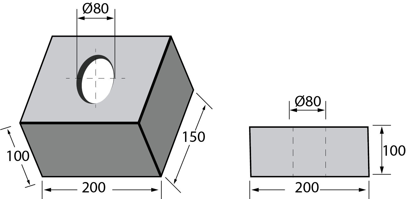
From the shrinkage allowance table above, the shrinkage allowance for steel is 21.0 mm/m.
For dimension 200, allowance is 200 * 21.0/1000 = 4.20 mm.
For dimension 150, allowance is 150 * 21.0/1000 = 3.15 = 3.20 mm (approximately).
For dimension 100, allowance is 100 * 21.0/1000 = 2.10 mm.
For dimension 80, allowance is 80 * 21.0/1000 = 1.68 = 1.70 mm (approximately).
Therefore, the pattern with required dimensions taking shrinkage into account is shown below:
2.2 Finish or Machining Allowance
Extra material is provided to the pattern which is subsequently removed by machining or cleaning process because the finish and accuracy achieved in sand casting are generally low.
This may range from 2 to 20 mm.
The type of machining allowance provided would depend on the metal cast, the type of moulding used, the class of accuracy required on the surface and the complexity of surface details.
The machining allowance provided ultimately has to be removed by machining. Hence, the cost of providing additional machining allowance should be carefully examined before finalizing.
Machining Allowances on patterns for sand castings
| Dimension, mm | Allowance, mm | Allowance, mm | Allowance, mm |
|---|
| Bore | Surface | Cope Side |
| --------------- | --------------- | --------------- | --------------- |
| Cast Iron | | | |
| up to 300 | 3.0 | 3.0 | 3.0 |
| 301 to 500 | 5.0 | 4.0 | 6.0 |
| 501 to 900 | 6.0 | 5.0 | 6.0 |
| --------------- | --------------- | --------------- | --------------- |
| Cast Steel | | | |
| up to 150 | 3.0 | 3.0 | 6.0 |
| 151 to 500 | 6.0 | 5.5 | 7.0 |
| 501 to 900 | 7.0 | 6.0 | 9.0 |
| --------------- | --------------- | --------------- | --------------- |
| Non-ferrous | | | |
| up to 200 | 2.0 | 1.5 | 2.0 |
| 201 to 300 | 2.5 | 1.5 | 3.0 |
| 301 to 900 | 3.0 | 2.5 | 3.0 |
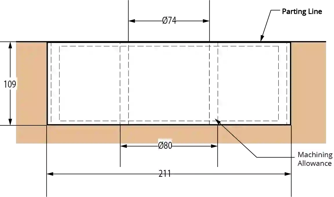
Question 2
From the Machining allowances table above:
- Machining allowance for bore = 3 mm
- Machining allowance for all surfaces = 3 mm
- Machining allowance for cope side = 6 mm
For the dimension 80, 80 + 2 * 3 = 86 mm.
For the dimension 100, 100 + 3 + 6 = 109 mm.
For the dimension 150, 150 + 3 + 3 = 156 mm.
For the dimension 200, 200 + 5.5 + 5.5 = 211 mm.
Therefore, the final dimensions are shown in the figure below:
2.3 Draft Allowance
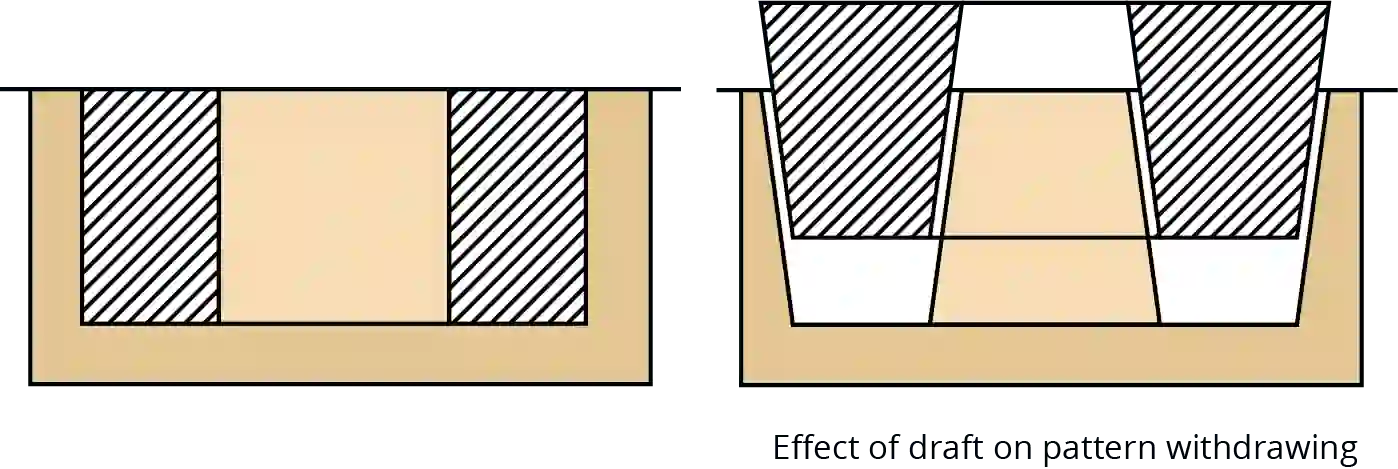
At the time of withdrawing the pattern from the sand mould, the vertical faces of the pattern are in continual contact with the sand which may damage the mould cavity. To reduce its changes, the vertical faces of the pattern are always tapered from the parting line. This provision is called the draft allowance.
Suggested Draft Values for patterns
| Pattern Material | Height if the Given Surface, mm | Draft Angle of Surfaces, Degrees | Draft Angle of Surfaces, Degrees |
|---|
| External Surface | Internal Surface | |
| --------------------- | -------------------------------- | --------------------------------- | --------------------------------- |
| Wood | | | |
| Wood | 20 | 3.00 | 3.00 |
| Wood | 21 to 50 | 1.50 | 2.50 |
| Wood | 51 to 100 | 1.00 | 1.50 |
| Wood | 101 to 200 | 0.75 | 1.00 |
| Wood | 201 to 300 | 0.50 | 1.00 |
| Wood | 301 to 800 | 0.50 | 1.75 |
| Wood | 801 to 2000 | 0.35 | 0.50 |
| Wood | over 2000 | - | 0.25 |
| Metal and Plastic | | | |
| Metal and Plastic | 20 | 1.50 | 3.00 |
| Metal and Plastic | 21 to 50 | 1.00 | 2.00 |
| Metal and Plastic | 51 to 100 | 0.75 | 1.00 |
| Metal and Plastic | 101 to 200 | 0.50 | 0.75 |
| Metal and Plastic | 201 to 300 | 0.50 | 0.75 |
| Metal and Plastic | 301 to 800 | 0.35 | 0.50 |
Question 3
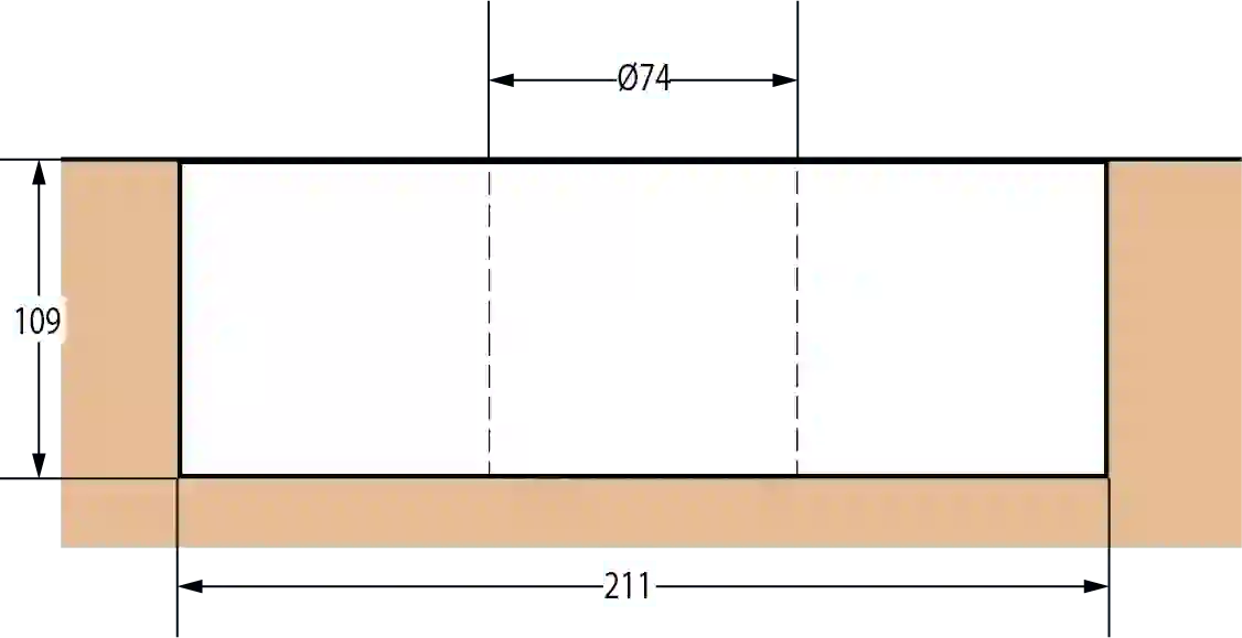
Remember we provided machining allowance to the above pattern in Question 3. Now provide draft allowance to the above pattern. Take the help of the table above.
Answer: Try to solve this problem yourself and send your answers to info@intromech.com
2.4 Shake Allowance
Before withdrawal from the sand mould, the pattern is rapped all around the vertical faces to enlarge the mould cavity slightly which facilitates its removal. Since it enlarges the final casting made, it is desirable that the original pattern dimensions should be reduced to account for this increase. There is no sure way of quantifying this allowance since it is highly dependent on the foundry personnel and practices involved.
It is a negative allowance and it is to be applied only to those dimensions which are parallel to the parting plane.
One way of reducing this allowance is to increase the draft which can be removed during the subsequent machining.
2.5 Distortion Allowance
A metal when has just solidified is very weak and therefore is likely to be distortion prone. This is particularly so for weaker sections such as long flat portions, V, U sections or in a complicated casting which may have thin and long sections connected to thick sections. The foundry practice should be to make extra material provision for reducing the distortion. Alternatively, the shape of the pattern itself should be given a distortion of an equal amount in the opposite direction of the likely distortion direction. This can be done by trial and error basis to get the distortion amount. Some data about a few test cases may be available from the literature.
Acknowledgements
All the information in this article is taken from the book Manufacturing Technology (Volume 1) by P.N. Rao.
MANUFACTURING TECHNOLOGY (Volume 1) relates to the practice of manufacturing with as much of scientific aspects as possible. This is a very comprehensive book on the technologies of Foundry, Forming and Welding. The book also has a separate special chapter on Previous GATE Questions and Solutions. You can also buy the ebook version from amazon. Manufacturing Technology by PN Rao PDF is available on amazon.