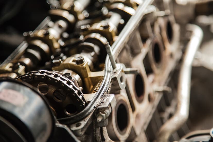
In this article, I will explain to you the first inversion of the slider-crank mechanism which is used in the engine to rotate the crank, as a result, the wheels of the vehicle rotate.
But before trying to understand this concept you should have some knowledge about kinematic links, kinematic chains, kinematic pairs, and a four-bar chain. These concepts are very easy and should not take more than 20-30 mins to master. I will try to write about these topics soon in other articles so stay tuned. But as of now, there are many resources on the internet where you can learn concepts of kinematic links, kinematic chains, kinematic pairs, and four-bar chain. So go ahead read that and come here to learn about the slider-crank mechanism. I have also included two CAD models to help you understand better.
Slider-Crank Chain
It is a four-bar chain with one of the turning pairs replaced by a sliding pair. Or you can say: When one of the turning pairs of a four-bar chain is replaced by a sliding pair, it becomes a single slider crank chain.
A mechanism is a closed kinematic chain with one of its links fixed. We can fix any link at a time, so from the same chain, we get a different mechanism.
Kinematic Inversion
Before learning about the first inversion of the slider-crank chain let us know what a kinematic inversion is. Kinematic inversion means that the process of fixing different links of the same kinematic chain to produce different mechanisms. The most important thing about this process of kinematic inversion is that the relative motion between various links is independent of the kinematic inversion. So as long as the chain is the same, the relative motion between various links remains the same, independent of which particular link is kept fixed.
Inversions of Slider-Crank Chain
Similarly, by fixing different links at a time of a slider-crank chain we get its inversions.
The following are the inversions of the slider-crank chain.
- First Inversion: Link 1 is fixed, link 2 is made crank and link 4 is made the slider.
- Second inversion: Link 2 is fixed, link 3 becomes the crank and link 4 is the slider.
- Third Inversion: Link 3 is fixed, link 2 becomes the crank and link 4 the slider.
- Fourth inversion: This is obtained when the link 4 is fixed.
In this article, we are only discussing the first inversion. I will explain the other inversions in other articles.
First Inversion of Slider-Crank Chain
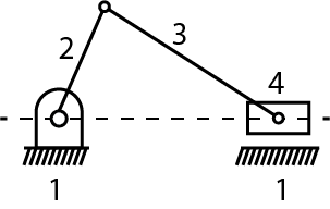
This inversion is obtained when link 1 is fixed and links 2 and 4 are made the crank and the slider respectively. The applications of the first inversion can be seen in the reciprocating engine and the reciprocating compressor. In the reciprocating engine, the piston is the driver whereas as in reciprocating compressor the crank is the driver.
To understand more clearly consider the model given below.
In this model, the Plummer Block (blue color) is the fixed link 1. The crank (green color) is link 2. The piston (yellow color) is the link 4. Connecting rod (red color) is link 3 connecting the crank (link 2 ) and the piston (link 4). The reciprocating motion of the piston results in the rotation of the crank.
Here's another example of the first inversion of the slider-crank chain.
As you can see in the above mechanism, the reciprocating motion of the slider results in the rotation of the crank and vice versa.